Concrete pumping pipeline risks
Issued: 14 August 2009
Last Updated: 14 August 2009
Purpose
The purpose of this safety alert is to highlight the issue of pipeline failure on concrete pumps, and to provide guidance on ways to minimise this risk.
Background
A number of incidents associated with the failure of concrete delivery pipelines have occurred in Queensland including:
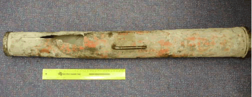
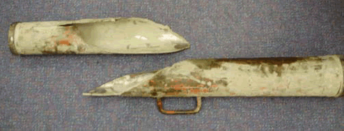
- Catastrophic failure of a pipeline reducer1 resulting in the explosion of concrete and steel at high speed (refer to photographs).
- Pipe clamps failing under pressure causing the pipeline to fail at the joint between the two pipes, resulting in concrete being sprayed at high pressure.
- Inspection caps on T pieces' or elbows around the hopper area of the pump blown off due to pipe clamp failure.
- The failure of steel pipelines due to excessive wear or the use of pipe that does not have adequate pressure rating for the pressure applied by the concrete pump.
- Rubber delivery hoses dropping off the end of concrete placement booms due to inadequate securing, that is, failure of clamps and safety chains not fitted properly.
Note 1: note a reducer is a segment of tapered pipeline that reduces the diameter of the delivery pipeline to allow easier placement of concrete e.g. from 125 mm to 100 mm diameter.

Photograph 1: Failed reducer

Photograph 2: Failed reducer - exploded view
Recommended control measures
Specific guidance relating to the safety of concrete delivery pipelines includes:
- Pipeline and reducers
The working pressure of the pipe and reducer must exceed the maximum pressure applied by the pump. Factors of safety for the concrete delivery pipeline should comply with those specified in Australian Standard 1418.15.
Concrete delivery pipe, including the reducer should be identifiable through a unique identification code that corresponds to documented records on the concrete pump. It is preferable that the pipe is also marked with a manufacturer's name (or trademark) and a pressure rating. Documented information on the correct pipe specification, determined by the concrete pump manufacturer, must be kept with the concrete pump. The numbering of the pipe should be sequential from the hopper end (i.e. lowest number at the hopper end increasing along the length of the boom).
Pipe should be removed from the pump and discarded before it reaches its minimum thickness allowance as specified by the concrete pump manufacturer for the grade and type of pipe being used. In the case of single wall pipe, actual thickness readings are to be taken and recorded in a log book at intervals not exceeding one month (i.e. using a calibrated ultrasonic thickness tester).
Thickness of twin wall pipe cannot be easily checked unless pipe clamps are removed and an internal inspection is made. Wear rates on twin wall pipe will generally be less than single wall pipe however a documented system to reduce the risk of pipeline failure should be implemented for any pipe. In the case of twin wall pipe, internal inspections should also be carried out to verify if the pipe is wearing at the predicted rate. The discard procedure should not be based solely on assuming that the pipe can safely withstand a specific volume of concrete prior to being removed and discarded. - Pipe clamps
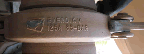
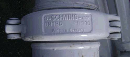
Pipe clamps should be permanently marked with the manufacturer's name (or trademark) and the maximum permissible operating pressure in Bar or Pressure Nominal (PN). Photographs 3 and 4 display clamps that are appropriately marked. The clamps must be rated at a higher working pressure than the maximum working pressure of the concrete pump. Pipe clamps that have worn pins, cracks, deformations or any other signs of excessive wear must not be used. The pipe clamps should be inspected for wear and damage before each use. Quick release clamps must be fitted with locking pins to ensure inadvertent release does not occur.

Photograph 3: An example of acceptable marking on pipe clamps.

Photograph 4: An example of acceptable marking on pipe clamps.
- Inspection caps
The risk of the end cap blowing off and causing injury to persons is to be adequately controlled. Appropriate control measures include well maintained high pressure clamps and a securely anchored safety chain fitted to the inspection cap.
Further information
Detailed information regarding the safety of pipelines on concrete pumps can be found in the Concrete pumping code of practice 2019 (PDF, 1.04 MB). The Code of Practice also refers to principles in the Australian Standards that relate to concrete pumping AS 1418.15 Cranes: Concrete Placing Equipment and AS 2550.15 Cranes - Safe use: Concrete Placing Equipment.